Relational Model
- Data relation
represented in the form of tablewith columns and rows are called Relational Model - Tuple
- Each row is known as a
tuple
- Each row is known as a
- Columns
- It represents the attributes of the relation
- Each attribute, there is a
permitted value, called domainof the attribute.
- Cardinality
- Total number of tuples in a given relation.
- Degree of table
- Number of attributes/columns in a given table/relation.
- A relational DB consists of
collection of tables, each of which is assigned a unique name.Software that implemented Relation model is RDBMS- Eg: Oracle, IBM, MySQL, MS Access
- Relation Schema
- It defines the design and structure of the relation, contains the name of the relation and all the columns/attributes.
- Relational Key
- Set of attributes which can uniquely identify an each tuple.
- Comparison with ER-Model
- Entity –> Table
- Attribute –> Column
- Relation –> Foreign Key (FK)
Important properties of a Table in Relational Model
- The name of relation is distinct among all other relation.
- The values have to be atomic. Can’t be broken down further.
- The name of each attribute/column must be unique.
- Each tuple must be unique in a table.
- The sequence of row and column has no significance.
- Tables must follow integrity constraints - it helps to maintain data consistency across the tables.
Relational Model Keys
- Super Key (SK)
- Any Permutation & Combination of attributes present in a table which can
uniquely identifyeach tuple.
- Any Permutation & Combination of attributes present in a table which can
- Candidate Key (CK)
Minimum subset of super keys, which can uniquely identify each tuple.- It contains no redundant attribute.
- CK value shouldn’t be NULL.
- Primary Key (PK)
- An
single attributes that can uniquely identifyeach tuple
- An
- Alternate Key (AK)
- All CK except PK.
- Foreign Key (FK)
- It
creates relation between two tables - PK of Table T1 is used as attribute of another Table T2
- This attribute in T2 is referred as FK
- FK helps to cross-reference between two different relations.
- It
- Composite Key
- PK formed using at least
2 attributes
- PK formed using at least
- Compound Key
- PK which is formed
using 2 FK
- PK which is formed
- Surrogate Key
- Synthetic PK.
Generated automatically by DB, usually an integer value.- May be used as PK.
Integrity Constraints
- CRUD Operations must be done with some integrity policy so that DB is always consistent.
- Introduced so that we do not accidentally corrupt the DB.
- Domain Constraints
Restricts the valuein the attribute of relation, specifies the Domain.- Restrict the
Data typesof every attribute. - E.g. birth year < 2002
- Entity Constraints
- Every relation
should have PK - PK != NULL
- Every relation
- Referential Constraints
- Specified between two relations & helps maintain consistency among tuples of two relations.
- Insert Constrain
- Delete Constrain
Whenever the referenced object is deletedwe have the following option to maintain Delete constrain
- CASCADE
- The
objects referencing it are deletedas well
- The
- SET_NULL
- Set the
ForeignKey to null
- Set the
- SET_DEFAULT
- Set the ForeignKey to its
default value
- Set the ForeignKey to its
- DO_NOTHING
- Do nothing - Consistency must be handled elsewhere
- Key Constraints
- The six types of key constraints present in the Database management system are:-
- NOT NULL
- This constraint will restrict the user from
not having a NULL value - It ensures that every element in the database has a value.
- This constraint will restrict the user from
- UNIQUE
- It helps us to ensure that all the values consisting in a
column are different from each other
- It helps us to ensure that all the values consisting in a
- DEFAULT
- It is used to
set the default valueto the column. - The default value is added to the columns if no value is specified for them.
- It is used to
- CHECK
- It is one of the integrity constraints in DBMS.
- It keeps the
check that integrity of data is maintainedbefore and after the completion of the CRUD.
- PRIMARY KEY
- This is an attribute or set of attributes that can uniquely identify each entity in the entity set.
- The primary key must contain unique as well as not null values.
- FOREIGN KEY
- Whenever there is some relationship between two entities, there must be some common attribute between them.
- This common attribute must be the primary key of an entity set and will become the foreign key of another entity set.
- This key will prevent every action which can result in loss of connection between tables.
Transform - ER Model to Relational Model
- Both ER-Model and Relational Model are abstract logical representation of real world enterprises.
- Because the two models implies the similar design principles, we can convert ER design into Relational design.
- Converting a DB representation from an ER diagram to a table format is the way we arrive at Relational DB-design from an ER diagram.
ER diagram notations to relations:
- Strong Entity
Becomes an individual tablewith entity name, attributes becomes columns of the relation.- Entity’s Primary Key (PK) is used as Relation’s PK.
- FK are added to establish relationships with other relations.
- Weak Entity
- A table is formed with all the attributes of the entity.
- PK of its corresponding
Strong Entity will be added as FK - PK of the relation will be a composite PK, {FK + Partial discriminator Key}.
- Single Values Attributes
- Represented
as columns directlyin the tables/relations.
- Represented
- Composite Attributes
- Handled by
creating a separate attributeitself in the original relation for each composite attribute. - E.g., Address: {street-name, house-no}
- address-street-name & address-house-name as new columns in the existing table and ignore “address” as an attribute.
- Handled by
- Multivalued Attributes
New tables are createdfor each multivalued attribute.- PK of the entity is used as column FK in the new table.
- Multivalued attribute’s similar name is added as a column to define multiple values.
- PK of the new table would be {FK + multivalued name}.
- e.g., For Strong entity Employee, dependent-name is a multivalued attribute.
- New table named dependent-name will be formed with columns emp-id, and dname.
- PK: {emp-id, name}
- FK: {emp-id}
- Derived Attributes
Not considered in the tables
- Generalisation
- For e.g., Banking System generalisation of Account - saving & current.
- Method-1:
- Create 3 tables
- Table 1: account (account-number, balance)
- Table 2: savings-account (account-number[FK], interest-rate, daily-withdrawal-limit)
- Table 3: current-account (account-number[FK], overdraft-amount, per-transaction-charges)
- Method-2
- Create 2 tables
- Table 1: savings-account (account-number, balance, interest-rate, daily-withdrawal-limit)
- Table 2: current-account (account-number, balance, overdraft-amount, per-transaction-charges)
- Drawbacks of Method-2
- Common/overlapping attribute
- Aggregation
Table of the relationship set is made- Attributes includes primary keys of entity set and aggregation set’s entities.
- Also, add descriptive attribute if any on the relationship.

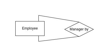
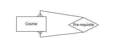
- Unary Relationship
- 1:1 Unary relationship

- M:N Unary relationship

- 1:1 Unary relationship


