# Topic covered
* OSI Model
  * Physical, Data-link Layer
  * Network Layer
  * Transport Layer
  * Session, Presentation, Application Layer
* TCP/IP model
2.1 OSI Model
The OSI Model (Open Systems Interconnection Model) is a conceptual framework used to describe the functions of a networking system.
The OSI model characterizes computing functions into a universal set of rules and requirements in order to support interoperability between different products and software.
It has been developed by ISO – International Organization for Standardization, in the year 1984
In the OSI reference model, the communications between a computing system are split into seven different abstraction layers:
Physical, Data Link, Network, Transport, Session, Presentation, and Application.
| Layer | Data Unit | Devices |
|---|---|---|
| Application Layer | Data | Firewalls, PC, Phones |
| Presentation Layer | Data | Firewalls |
| Session Layer | Data | Firewalls |
| Transport Layer | Segments | Gateway Firewall |
| Network Layer | Packets | Router |
| Data-link Layer | Frames | Switch, Bridge, NIC |
| Physical Layer | Bit Stream | Hub, Repeater, Modem, Cables |

Layer 1: Physical Layer
The lowest layer of the OSI reference model is the physical layer.
It is responsible for the actual physical connection between the devices.
The physical layer contains information in the form of bits
The bit stream transmitted over physical medium(copper - electrically, optical - light, wireless - Electromagnetic waves)
- Functions
Line Configuration- how two or more devices can be connected physically.Data Transmission- it defines the transmission mode whether it is simplex, half-duplex or full-duplexTopology- how network devices are arranged.Encoding- type of the signal used for transmitting the information
- Hardware used: Hub, Repeater, Modem, Cables
- Data unit:
Bit Stream
Layer 2: Data-link Layer
The data link layer is responsible for the node-to-node delivery of the message.
The main function of this layer is to make sure data transfer is error-free from one node to another, over the physical layer
- Functions
Delivery- Node-to-Node(Router-to-Router) delivery of the messageFraming- The data link layer translates the physical’s raw bit stream into packets known as FramesPhysical addressing- After creating frames, the Data link layer adds physical addresses (MAC address) in the header of each frame.Error control- Node-to-Node Error Control(CRC)Flow control- Node-to-Node flow control(Stop & wait, Sliding window, HDCL)Access control- which device has control over the channel at a given time (CSMA/CD, Aloha, Token-ring)
- Hardware used: Switch & Bridge
- Data unit:
Frames
Layer 3: Network Layer
The network layer works for the transmission of data from one host to the other located in different networks.
It also takes care of packet routing i.e. selection of the shortest path to transmit the packet, from the number of routes available.
The sender & receiver’s IP addresses are placed in the header by the network layer.
- Functions
Delivery- Host-to-Host / Source-to-Destination / Machine-to-Machine DeliveryLogical Addressing- The sender & receiver’s IP addresses are placed in the header by the network layer.Routing- determines the best optimal path (RIP, OSPF)Fragmentation- Frames are divided into Packets
- Hardware used: Routers
- Protocol used: IP, NAT, ARP, ICMP, DHCP
- Data unit:
Packets
Layer 4: Transport Layer
The transport layer provides services to the application layer and takes services from the network layer.
The data in the transport layer is referred to as Segments.
It is responsible for the End to End Delivery of the complete message.
The transport layer also provides the acknowledgement of the successful data transmission and re-transmits the data if an error is found.
- Functions
Delivery- End-to-End / Port-to-Port DeliverySegmentation- Segment the data and forward to Network LayerFlow control- End-to-End flow control(Stop & wait, Sliding window, HDCL)Error control- End-to-End Error Control(Checksum)
- Protocol used: TCP, UDP,
- Hardware used: Transport Gateway
- Data unit:
Segments
Layer 5: Session Layer
This layer is responsible for the establishment of connection, maintenance of sessions, authentication, and also ensures security.
- Functions
- Session - establishment, maintenance, termination
- Synchronization
- Data unit:
Data
Layer 6: Presentation Layer
The presentation layer is also called the Translation layer. The data from the application layer is extracted here and
manipulated as per the required format to transmit over the network.
- Functions
Translation- Format the data, eg: ASCII to EBCDIC.Encryption/Decryption- cipher and de-cipher the dataCompression- Reduces the number of bits that need to be transmitted on the network
- Data unit:
Data
Layer 7: Application Layer
It is the very top layers of the OSI Model. These applications produce the data, which has to be transferred over the network.
This layer also serves as a window for the application services to access the network and for displaying the received information to the user.
- Function
- Produce the data
- Display the received data
- Hardware used: Application Gateway
- Protocol used: HTTP, SMTP, POP3, FTP, DNS, TELNET
- Data unit:
Data

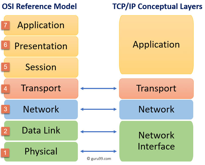
2.2 TCP/IP model
https://www.guru99.com/tcp-ip-model.html
TCP/IP stands for Transmission Control Protocol/ Internet Protocol, It is a concise version of the OSI model.
It is developed by ARPANET (Advanced Research Project Agency Network).
It contains four layers, unlike seven layers in the OSI model.
The OSI Model we just looked at is just a reference/logical model.

- Network Access/Interface Layer
- A network layer is a
combination of the Physical and Data linklayer of the OSI reference model.
- A network layer is a
- Internet/Network Layer
- Transport Layer
- Application Layer
- Application layer is a
combination of the Session, Presentation and Application layerof the OSI reference model. - Implementation of these 3 layers is done by the network application itself.
- These are also known as Upper Layers or Software Layers.
- Application layer is a


